Because my university period is now fare away behind me, my maths and electronic theory are very very rusty and U=R*I and P=U*I .are the only calculation i'm able to do without having to remember my maths :)
Of course browsing on the net give you access to an unlimited already calculated and working schematics but they can be very frustrating because you don't have the proper capacitor or resistor value to breadboard it. You can always tweak some value on your breadboard prototype but it can be very tedious and frustrating.
So why not simulating the circuit before breadboarding it?
Browsing on the net i found quite a lot of online circuit simulator like partsim, Circuit lab, falstad and plenty more.
Most of them look very similar and are based on spice model but they are all Online simulator cloud based with account creation and all the circus. which is not practical in my remote working environment where internet is everything but reliable.
This is a pretty cute java applet that give you a quick visual look on tons of electronic circuit.Very easy to use and no need of registration or what so ever. no add a well:)
Looking for stand alone circuit simulator i found out QUCS Quite univeral simulator
What's Qucs?
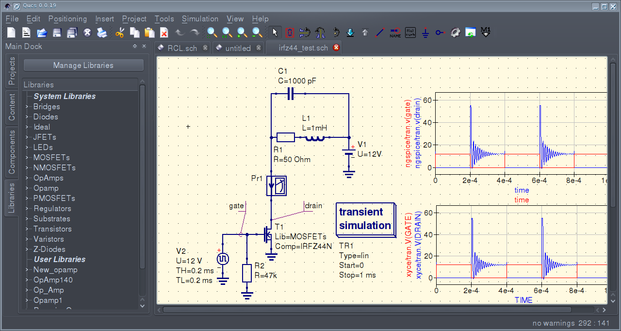
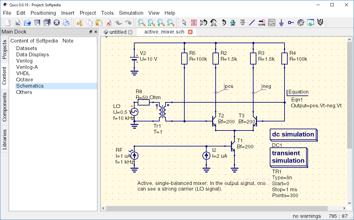
'Qucs stands for Quite Universal Circuit Simulator. So far Qucs is not yet finished, but it is already packed with features. Take a look at the screenshots to get a feel for what it can do.
Qucs is an integrated circuit simulator which means you are able to setup a circuit with a graphical user interface (GUI) and simulate the large-signal, small-signal and noise behaviour of the circuit. After that simulation has finished you can view the simulation results on a presentation page or window.
- Qucs, briefly for Quite Universal Circuit Simulator, is a circuit simulator with graphical user interface (GUI). The GUI is based on Qt® by Digia®. The software aims to support all kinds of circuit simulation types, e.g. DC, AC, S-parameter, Harmonic Balance analysis, noise analysis, etc.
- Qucsator, the simulation backend, is a command line circuit simulator. It takes a network list in a certain format as input and outputs a Qucs dataset. It has been programmed for usage in the Qucs project but may also be used by other applications.
The Qucs GUI is well advanced and allows setting up schematics and presenting simulation results in various types of diagrams. DC, AC, S-parameter, noise and transient analysis is possible, mathematical equations and use of a subcircuit hierarchy (with parameterised subcircuits) are available. Qucs can also import existing SPICE models for use in your simulations'....
...'While Qucs is well developed, we still strive to improve the project, and will always welcome offers of help. Qucs doesn't just need help with programming, it also needs graphics, high quality example schematics, tutorials for the website and lots more.
Qucs comes with a huge array of components and models including HICUM, BSIM2, BSIM3, and soon BSIM6. It also provides many semiconductor based components and models such as OpAmps, Diodes, MOSFETs, PMOSFETs and many more. Some example schematics can be found here which demonstrate some of the abilities of Qucs, and many more examples are provided with the program.'
My practical application of QUCS:
My bedside lamp just die. It was a thyristor like 40w dimmer lamp.
I would love to replace the 220vac thyristor dimmer by a 12Vdc led dimmed by a simple potentiometer.
Using the same principle as my previous project Transformerless Day/Night Controlled Led step light, I can power 8 led from my led strip roll via a transistor and dimmed it via a potentiometer.
What do i have in stock:
- 250k Ohm potentiometer scraped from my dead lamp
- 8 led from my led strip roll
- 1 transistor BC547b
- 1 NA02-T2S12 12VDC 2W power supply
My led strip sub circuit:
There is no components for my 8 strip led in the Qucs component library.
I have to make a sub circuit with qucs library component who behave as close as possible like my led load.
each led work in 12 v and use 18 ma and have an internal resistor. I assume that this kind of led is 3.6 V.
Looking in the Qucs component library i select the blue Led with 3.3V and 20ma.
each led in the sub circuit will be driven by a resistor of the following value: R=(12v-3.3V)/0.018A=483 Ohm
HighLedSub.sch
I now able to make a DC simulation using my sub circuit to validate my high led circuit.
I1 is a current probe to measure the current flowing in the circuit and the Parameter sweep is going to change the value of the DC power V1 from 1v to 12v in 1 v increment.
The sub component High led is pointing to the Qucs file of the led circuit already defined above HighLedSub.sch.
I can now run the DC simulation and draw the following diagram.
I can now draw my final circuit diagram including my BC 547 b transitor and my 250k potentiometer and run a DC simulation with a Parameter sweep changing the resistance of the potentiometer.
The parameter sweep is going tochange the rotation in degre of the pot in between 0 deg to max 240 deg ( as define in the pot component library wit a maximum resistance of 250k ohm of the pot.
I1 is going to measure the total current draw by the circuit.
I2 the current drawn by the pot and I3 the current drawn by the led sub circuit.
i had some Label Vpot to measure the voltage at the potentiometer output, Vbase to measure the base voltage of the transistor andVcol to measure the colector voltage of thetransistor.
Running the simulation in Qucs i can now draw the following diagrams:
Hurrah Hurrah !!!! It's seem to work.
The first diagram on the top left show me in blue the Vcol / Pot value.
At 0Ohm no current pass between collector and emitter. and 250 Ohm the transistor is saturated and 124ma flow in between collector and emitter and we have a nice curve in between 50 ohm and 200 ohm.
After bread boarding the circuit i measure the current with my tester between the led and the collector and obtain almost the same result
I1 =0.140ma vs 0.135ma from Qucs
and the lamp dim exactly as expected with a nice curve.
Conclusion:
The Bread board prototype work exactly like the Qucs simulation.
I can tweak any value from the simulation to emulate any behavior of the circuit without to have to burn down any components.
There is as well a good library of schematics located in the Qucssharedocqucs folder.
I assembled this circuit in my original bed lamp stand and i have now a dimmed led bed lamp of of 1.7W instead of the original 40W.


